After weeks of planning, I finally got the chance to test my setup for SSC7926 project for the first time. I’ll probably explain what is SSC7926 all about in one of the future posts, but for the time being it is my attempt to make a digital back for my medium format Bronica SQ camera using an ilx508 linear CCD.
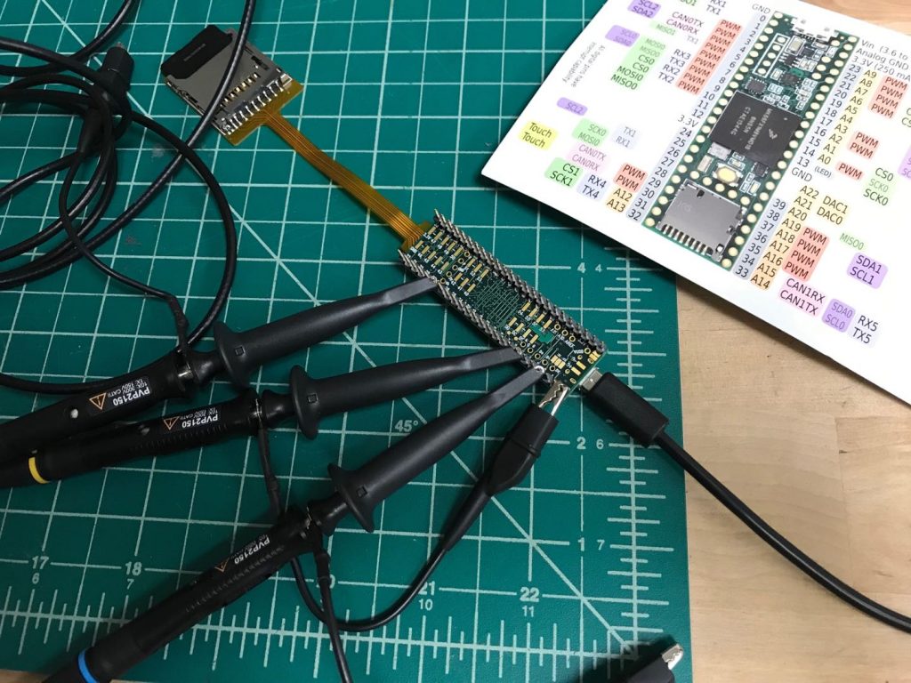
I plan to use a Teensy 3.6 to generate clock signals to drive the CCD, and sample the analog output from the sensor. For this proof of concept test, I used the Carrier Modulator Transmitter (CMT) on the k66 chip to generate the clock signal. CMT interrupt ISR was set up to start ADC sampling and conversion, and DMA was used to move the result of conversion to a buffer in memory. Every time the buffer was half-full, data were wrote to a SD card.
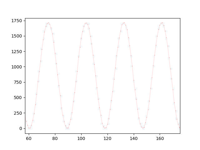
With this setup, I was able to achieve a sampling rate of 295 kHz at 16 bits (to get the 13 bits ADC resolution I had to sample at 16 bits, but lowering ADC resolution should allow me to sample a bit faster). Just for fun I hooked the board up to a 10 kHz sine wave from a signal generator, and got a pretty clean waveform. In its final form the ADC will be sampling in sync with the CCD output. Fast sampling rate is pretty high on the priority list in this project, since it determines how long one full imaging scan is going to be. According to my calculations, at 295 kHz it will take 3.6 min, and my target is around 3 minutes, with a lowest acceptable time of 5 minutes.
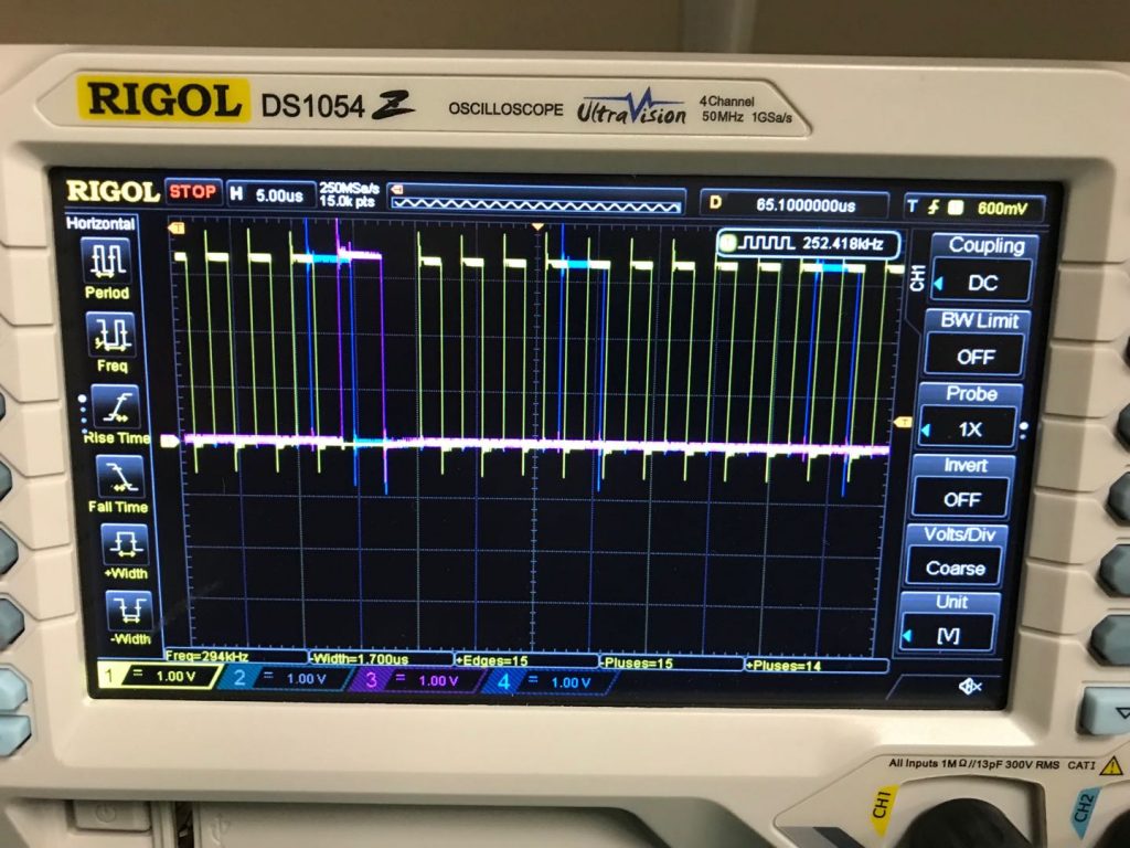
I also measured the clock signal timing and it seemed good. You can see the ROG signal was pulled high during the CLK signal missing pulse. STEP pulse was generated at regular intervals. The overshoot was probably due to the large loop between the grounding clip and the probes, but hey I’m an CS major and this is my first time using a oscilloscope so do’t but too harsh.
I’m pretty happy with this test. It’s good to know the ideas I came up with actually worked, and the project is somewhat feasible. Now I can move on to prototype the circuit and get the CCD running. Stay tuned for more updates.
The code for this test can be found here. Check out my Github repo for most recent developments. The python script for plotting the curve from the binary file can be found here.
 Text published under CC BY-SA 4.0