Another update about the linear CCD project. Last Friday we tested out the CCD for image generation. The clock and trigger signal are generated by Teensy and are fed into the CCD. CCD capture the light intensity and return the signal back to the amplifier. The amplifier output then is connected to the ADC pin on Teensy for sampling. The test method is crude — with 2.54mm pin headers on top of the CCD — to generate some shape… here’s the waveform seen on oscilloscope:
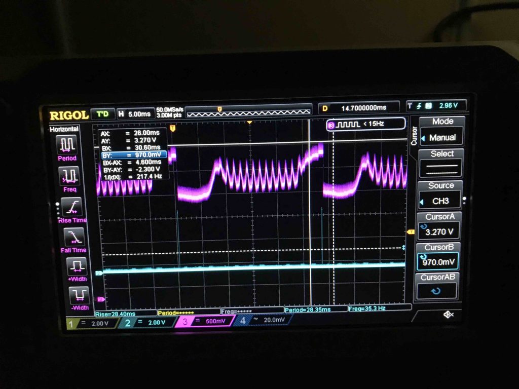
From the oscilloscope graph, we can clearly see the shape posed by the pin header onto the CCD, here’s the image:
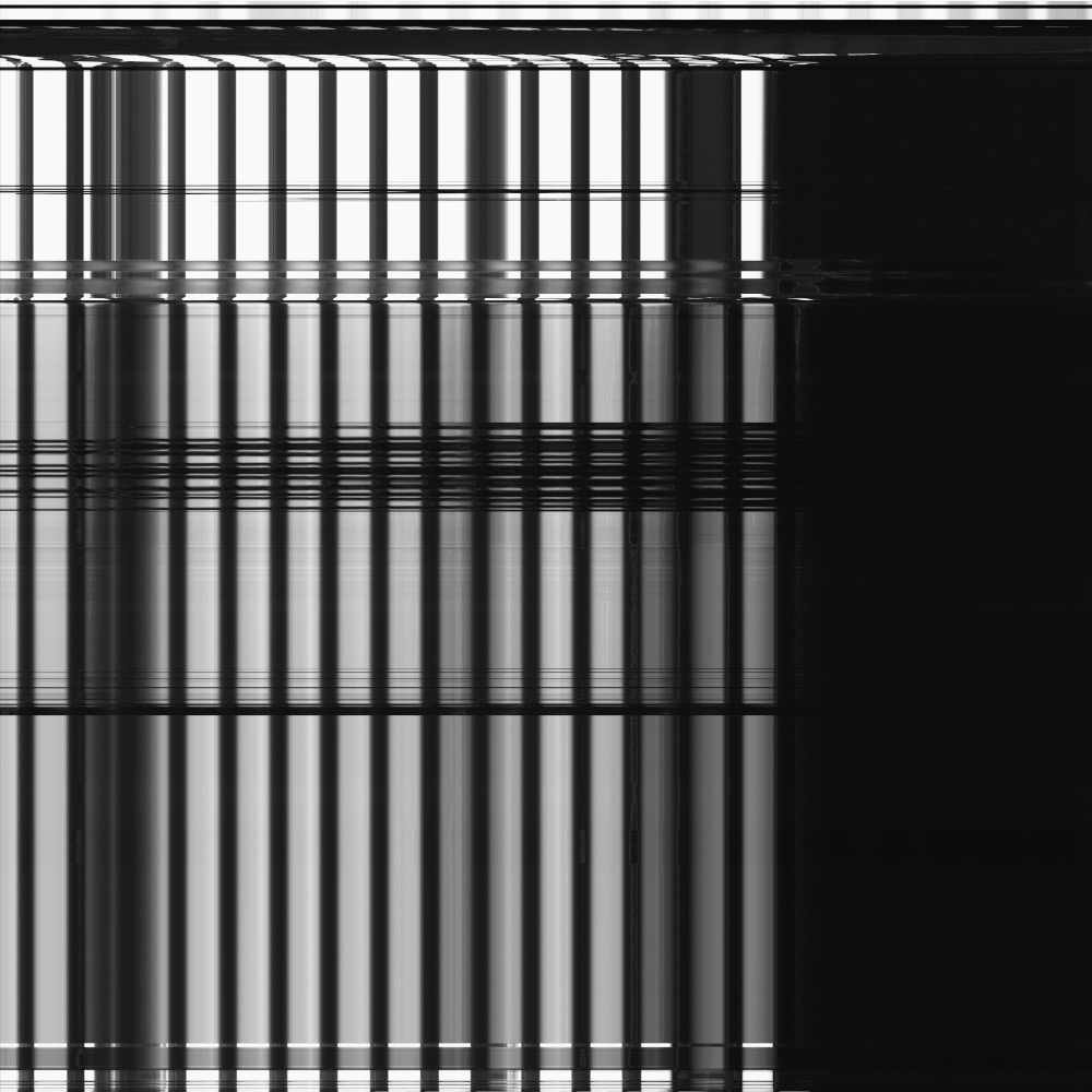
I know… it’s hideous, this is not what you expect with a functioning CCD (seems more like a broken one to me). However, this is actually pretty good, just hear me out.
The vertical back/white bars are from the 2.54mm pin header, and the horizontal bar is just our changing of light intensity. The right part is the optical black from the CCD signal as a reference point (dummy pixels). Overall, it is a pretty successful test and we (at least me) are happy about it. Yichi is making PCB for the CCD breakout board at this moment, we are planning to put the order by this weekend. We are also going to figure out the stepper motor part to make that CCD move horizontally. See you soon with more updates.
 Text published under CC BY-SA 4.0